FPGA LED Matrix Adventures
Back in 2015, I decided I wanted to do a cosplay for San Diego Comic Con. Given that I had no skills in sewing or costume making in general, this seemed a foolish decision, but it was an excellent excuse to learn! There was a character I quite liked in Saga named Prince Robot IV. And, as a less well-known reference, it also worked as "The One Electronic" from the comic Rice Boy (one of my favorite comics! Check it out!).
I really enjoy how emotional content was conveyed through the TV head. The thought was, I would build a TV head, and then worry about the rest of the costume later. I was, as you might expect, wholly unprepared for the amount of work this ended up being.
The project started with a combination of three elements which I hoped I could get working in conjunction:
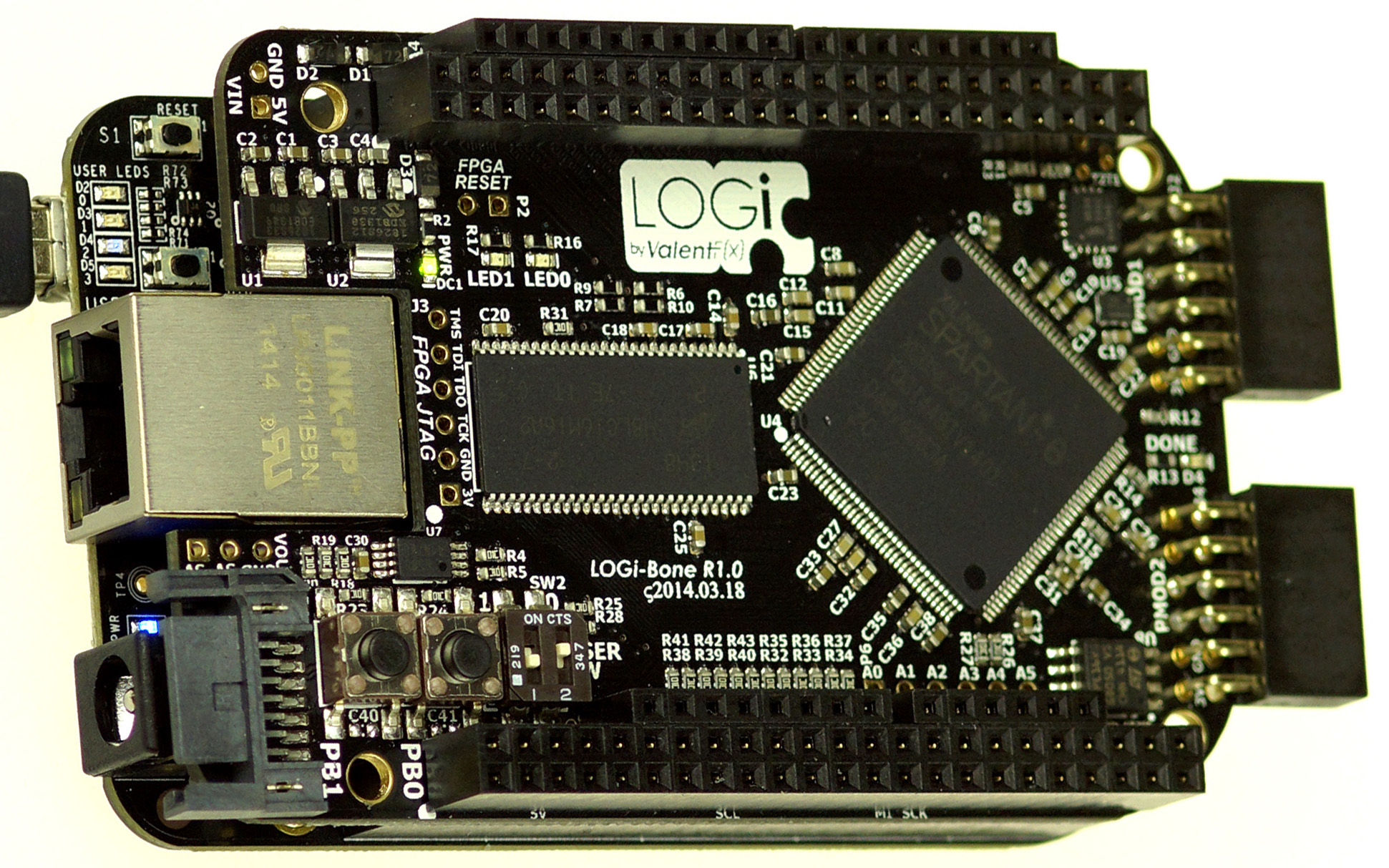
- The logibone - a Spartan 6 FPGA designed to connect to a Beaglebone Black
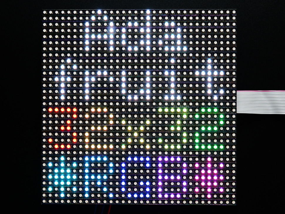
- 5mm pitch 32x32 RGB LED matrix from Adafruit
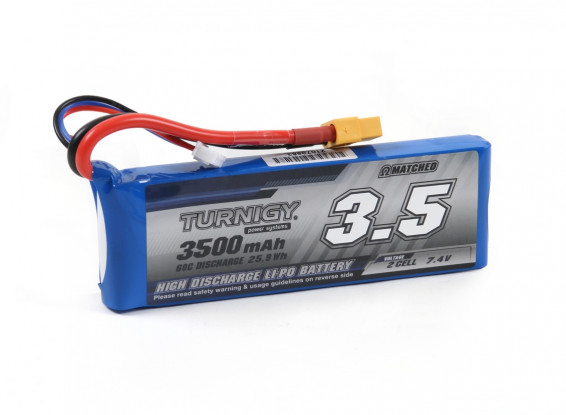
- Big lithium-ion battery pack
Why these particular components? Well - largely because I had impulse bought them at various points so they were already in my toolbox. There was also a comment on SparkFun's page:
These displays were intended for use with FPGAs and high-speed processors. We've found that 16MHz is about the slowest processor that can drive these adequately. If you want to daisy-chain them together, you will need more speed and more RAM.
Since I had always wanted to learn how to use FPGAs well, it also seemed like a good opportunity to work on my verilog skills. At the time, the documentation around these screens was almost nonexistant. To that end let's talk about how to interface with these panels, as I came to understand them!
The LED Matrix Screen Protocol "HUB75"
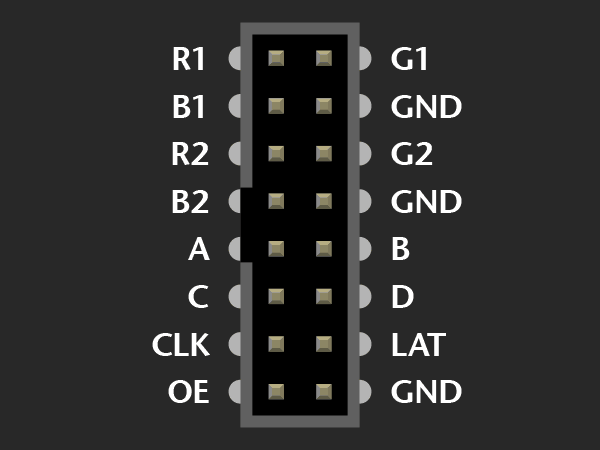
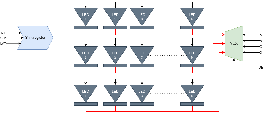
These screens do not have a "nice" interface like a WS2812 or similar addressable LED, the protocol is based on much simpler LED elements and demands that the driver board does all the work. To get an idea of what this entails, let's take a look at the pins we have on the LED panel:
The "R", "G", and "B" pins are for red, green, and blue color data, which is being passed in to serial-in-parallel-out shift registers. We have two sets of inputs because our panels display 2 rows worth of data at a time. A, B, C, and D are multiplexer inputs - they select which row we're controlling at any given time. Clock is the input for the shift registers. Latch is what signals to the shift register to move the most recent bits to the parallel outputs. And last, OE is "ouput enable" - whether or not the parallel outputs should drive the LEDs.
To rehash that as a flow of data rather than just a list of components - we shift in "full on" or "full off" as single bits of data to R1/G1/B1/R2/G2/B2. Once we've shifted out 32 clocks (for this display), we can then pulse the lat pin and it will then be ready to drive 2 complete rows. We can set which 2 rows as DCBA and DCBA+16. So if we want the 1st row and 16th row, we just set A, B, C, and D all low. Last but not least, we flip output enable high, and the 2 rows light up. Important to note here, is that there is not a set of drivers for each row. After doing all these steps, if we set A to 1, all the data we just put on the 1st and 16th rows will show on the 2nd row and 17th row! And this is only the flow to turn LEDs fully on and off! How do we control these LEDs?
How to PWM when we can't PWM
Normally, when confronted with an LED, to get shades between fully-on and fully-off, we would employ "pulse-width modulation" or PWM. PWM usually is a feature of a specific pin on the chip, and would need to be connected directly to the LED, but in this context we can only access the LED through the shift registers. So how do we get those shades? The answer is in repetition! We can run this interface at 25MHz line rate, which allows us to turn the whole row on and off thousands of times a second. To implement a PWM, we would keep track of a timer which was a multiple of the row length, and continuously shift out bits, comparing the value in each color and pixel against the global clock. The main downside to this method is that there is no break for other processing - every cycle you must be shifting out because there may be a pixel which is turning from "on" to "off" and since there is no clock per each pixel, we have to check the global clock against every pixel.
Another method is known as binary coded modulation (BCM) where the time held is done per bit, for 2^bit cycles. To show the differences between the 2, let's look at a timing diagram for a PWM and a BCM signal trying to output a value of 10 out of a maximum of 15 (4 bits of data):
A PWM signal outputs for 10 cycles, then turns off for the remaining 5. A BCM signal turns on for 8, off for 4, on for 2, and off for 1. Both methods take 15 cycles, and convey the same amount of on and off time, but they have decidedly different mechanisms for output from the driver. The main benefit to BCM, is that the driver can output the most significant bit, hold it for a number of cycles, then handle the next bit. Only the least significant bit has no break between drives, but the most significant bit can have a substantial break where the driver can be idle!
Update Rates
To make everything as smooth as possible, we want as high a framerate as possible. If we can get the framerate really high, we will also be able to minimize the number of artifacts people will see when trying to take video with a camera! "Really high framerate" in our case is in the ballpark of 200Hz, and "high framerate" is in the ballpark of 100Hz.
100Hz is a 10 ms period. That means we need to update each row at 10 ms/16 rows = 625 μS/row
At a 25MHz per pixel speed, and 32 pixels per row, we can update at (1/25 Mhz)* 32 = 1.28 μS/row
Then we layer on color depth: 625 / 1.28 = ~488 updates/row possible while staying within the 100Hz per screen update
rate.
Since we're working with binary numbers, that means we can get 8 bits of color (255 periods needed) but not 9 bits (511 periods needed).
This is perfect though - we don't need more than 8 bits of color per pixel! But then we get to the real challenge...
Daisy Chaining
This protocol actually allows screens to be daisy chained, and for this costume, I actually need 4 screens to cover the face. This meant I could only update at 1/4 of the speed listed above, because I would have 128 pixels per row instead of 32. At 5.12 μS/row as the maximum update speed, we get ~122 updates/row possible for a 100Hz update rate. This cuts down on the color depth to 6 bits of color per pixel! Fortunately this is still enough, but it's worth mentioning that one of the strengths of an FPGA is the ability to drive lots of pins in a controlled fashion. To this end, the FPGA could drive all the screens directly instead of daisy chaining, and we would have the ability to drive higher framerates or with more color depth. That being said - I didn't have enough time to modify my code and figure out pinouts to do this, so the costume did do daisy chaining.
The Code
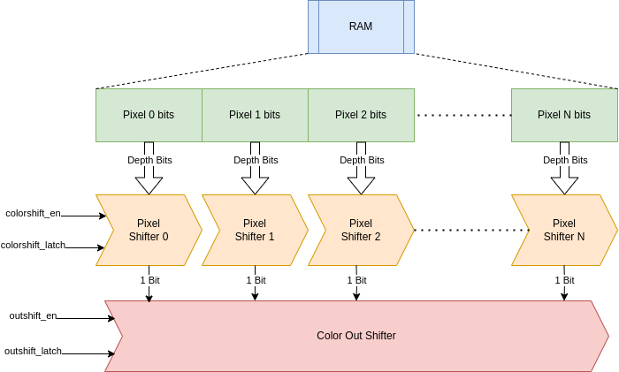
The code for this project is... kinda terrible! It was my first real verilog project, so try not to judge it too harshly. The code is based around copious amounts of shift registers arranged in a parallel channels. We control all the block ram through the same control channels, and the block ram feeds directly into the parallel-in, serial-out shift registers - 1 for each color of each pixel. Those shift registers then feed into a single large parallel-in, serial-out shift register which goes to the output pin. We control when we move the data in the pixel shift registers forward based on the count of how many cycles we expect each bit to be on.
With that overview, let's take a look at the code!
Starting things off, here's a pile of definitions we'll use throughout the code:
// All the local definitions!
localparam COLOR_BITS = 8; // Representable color (8bits per color per pixel)
localparam ROW_ADDR_BITS = 6; // 64 LEDs
localparam ROW_ELEM = (2**ROW_ADDR_BITS); // Number of LEDs in a row
localparam COL_ADDR_BITS = 4; // 16 rows
localparam COL_ELEM = (2**COL_ADDR_BITS); // Number of rows addressable by the MUX
localparam ROW_DAT_WIDTH = (ROW_ELEM * COLOR_BITS); // Number of bits to hold the data for 1 row

localparam DISP_COUNT = 2; // The number of 16 row displays in our setup
localparam PARALLEL_SHIFT = (DISP_COUNT * 3); // The number of shift registers output lines

localparam HUB_ENABLED = 1'b0;
localparam HUB_LATCH = 1'b1;
localparam SHIFT_LATCH_ON = 1'b1;
localparam SHIFT_EN_ON = 1'b1;
Next up we have the RAM-to-color-pixel pipeline - this ties together a block of ram to a parallel group of shift registers (one per pixel) to a whole row shifter.
// Generate a single color pixel pipeline
generate for (i = 0; i < PARALLEL_SHIFT; i= i + 50) begin : REDONELOOP
    wire [COL_ADDR_BITS - 1:0] ram_raddr;
    wire [ROW_DAT_WIDTH-1:0] ram_out; // We output X pixels at Y color depth all at once
    block_ram #( .RAM_WIDTH(ROW_DAT_WIDTH), .RAM_ADDR_BITS(COL_ADDR_BITS), .INIT_FILE("ram_red_1_init.txt")) pixel_ram (
        .clk(clk), .w_en(ram_wen[i]),
        .r_addr(ram_raddr), .w_addr(ram_waddr[i]),
        .in(ram_in[i]), .out(ram_out)
    );

    assign ram_raddr = cur_row; // We take a shared input for the current row

    wire [ROW_ELEM-1:0] color_shift_out; // the grouped output of all the pixel shifters
    parallel_shift #(.SHIFT_WIDTH(COLOR_BITS), .PARALLEL(ROW_ELEM)) color_shift (
        .clk(clk), .en(colorshift_en), .latch(colorshift_latch),
        .in(ram_out), .out(color_shift_out)
    );

    // This takes the ends of all the pixel shifters and groups them into a single output
    shift_reg #(.N(ROW_ELEM)) outshift (
        .clk(clk),
        .in(color_shift_out), .out(s_out[i]),
        .latch(outshift_latch),
        .en(outshift_en)
    );
end
endgenerate
Next up we have the meat of the code - the primary state machine! The logic is split into 2 intertwined state machines:
load_shift_latch- state machine with 4 states implied by the name: load new data from ram, shift data already available in the shifters, shift data from the outshifters onto the panel, and latch the data from the shifters into all the shift registers.bcm_count- a count of which bits we've shifted out of the pixel shifters. We use this to decide when to push forward the pixel shifters, as well as when to advance the current row
// Woooooo actual logic!
always @(posedge clk) begin
    load_shift_latch <= load_shift_latch + 1;

    // The "load" state
    if (load_shift_latch == 0) begin
        if (bcm_count == 0)
            hub_mux <= cur_row; // Bring the mux up to date with the RAM
        else if (bcm_count == 1)
            cur_row <= cur_row + 1; // Get the RAM to fetch the next row

        outshift_latch <= ~SHIFT_LATCH_ON;
        outshift_en <= SHIFT_EN_ON;

        hub_latch <= HUB_LATCH; // Latch the ouput from the previous cycle
        hub_oe <= HUB_ENABLED; // Turn on the display!
    end
    // load_shift_latch == 1 means we've clocked out 1 bit
    else if (load_shift_latch == 1) begin
        if (bcm_count == 1) begin
            colorshift_en <= SHIFT_EN_ON; // Put the 2nd bit of the current row on the shifter
        end
        else if (bcm_count == 5) begin
            colorshift_en <= SHIFT_EN_ON; // Put the 3rd bit of the current row on the shifter
        end
        else if (bcm_count == 13) begin
            colorshift_en <= SHIFT_EN_ON;
        end
        else if (bcm_count == 29) begin
            colorshift_en <= SHIFT_EN_ON;
        end
        else if (bcm_count == 61) begin
            colorshift_en <= SHIFT_EN_ON;
        end
        else if (bcm_count == 125) begin
            colorshift_en <= SHIFT_EN_ON;
        end
        else if (bcm_count == (2**COLOR_BITS)-2) begin
            colorshift_latch <= SHIFT_LATCH_ON; // Put the 0th bit of the next row on the shifter
        end
        else if (bcm_count == (2**COLOR_BITS)-1) begin
            colorshift_en <= SHIFT_EN_ON; // Put the 1st bit of the next row on the shifter
            hub_oe <= ~HUB_ENABLED;
        end

        hub_latch <= ~HUB_LATCH;
    end
    // load_shift_latch == 2 means we've clocked out 2 bits
    else if (load_shift_latch == 2) begin
        colorshift_latch <= ~SHIFT_LATCH_ON;
        colorshift_en <= ~SHIFT_EN_ON;
    end
    // load_shift_latch == 3 means we've clocked out 3 bits
    // load_shift_latch == 4 means we've clocked out 4 bits
    // ...
    // load_shift_latch == (ROW_ELEM - 1) means we've clocked out (ROW_ELEM - 1) bits
    // load_shift_latch == (ROW_ELEM) means we've clocked out (ROW_ELEM) bits
    else if (load_shift_latch == ROW_ELEM) begin
        outshift_latch <= SHIFT_LATCH_ON; // Get the next bit latched into the outshifter
        outshift_en <= ~SHIFT_EN_ON;

        load_shift_latch <= 0; // Reset the clock counter
        bcm_count <= bcm_count + 1; // Increment the number of rows shifted
    end
end
There's more to look at in the codebase there were a few refactors and rounds of code which made the code both more
compact and less scrutible. The branch which contains the version which went on the costume is spartan_6 which you
can see here.
The Physical Build
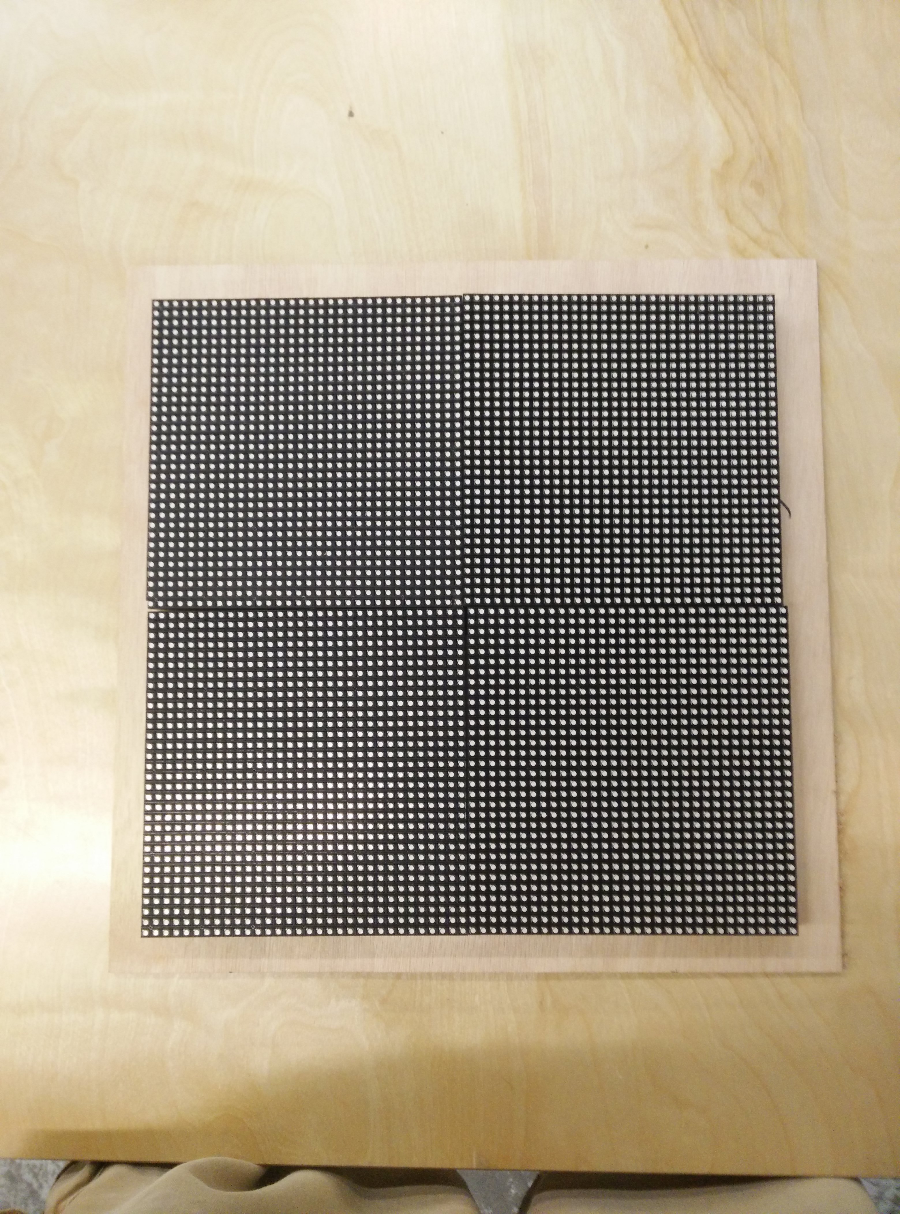
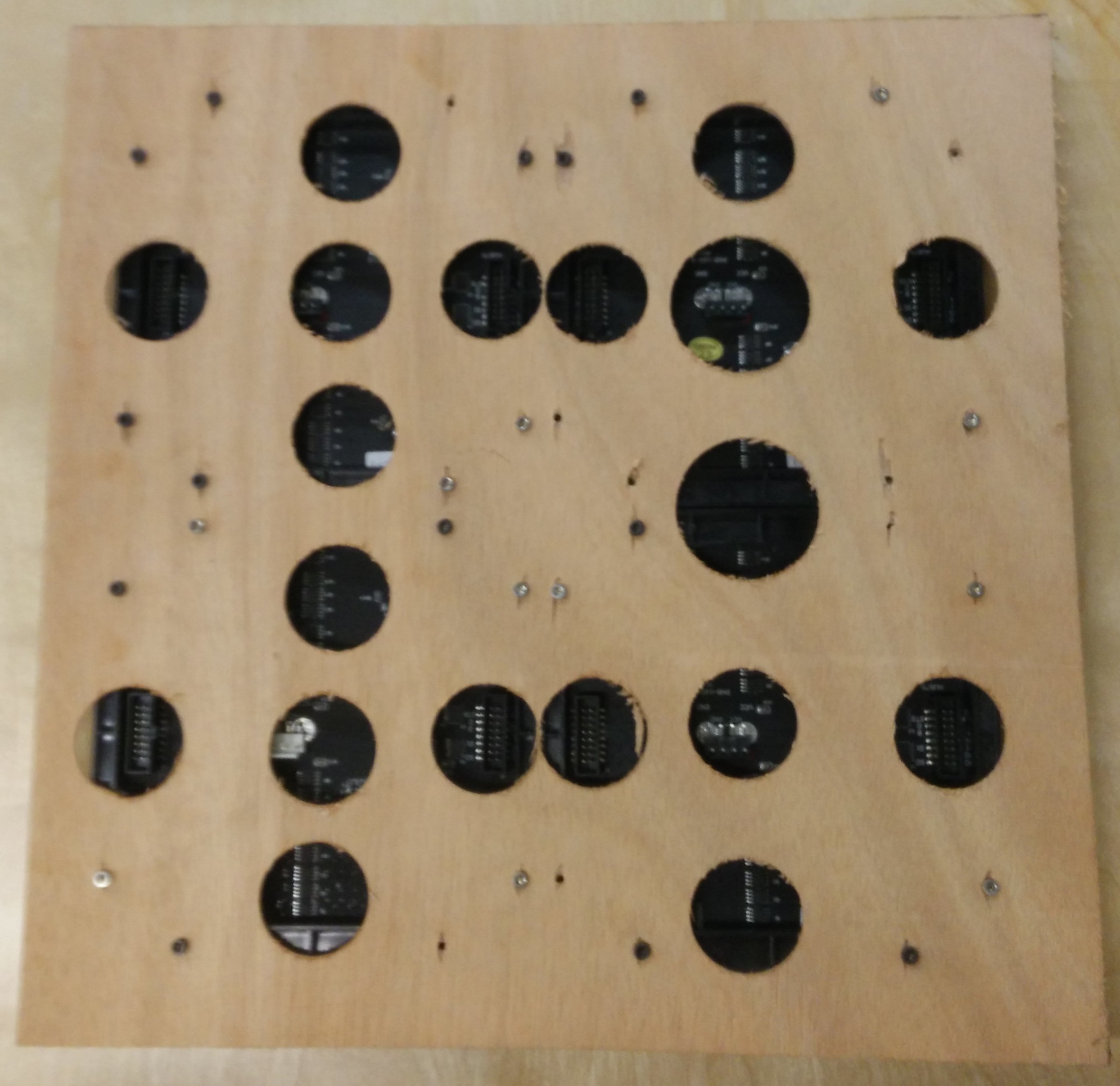
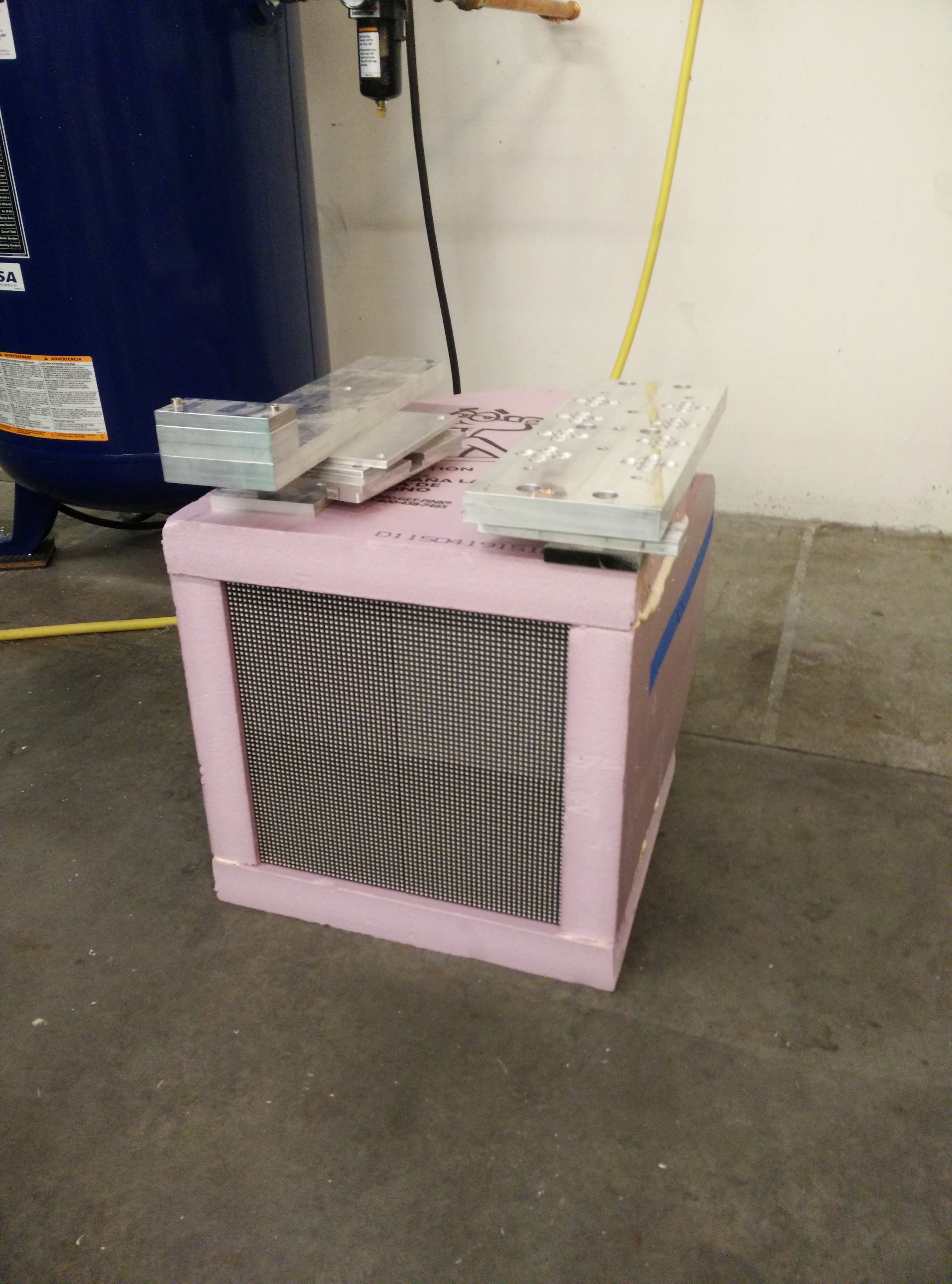
The build is made up of a total of 4 of the 32x32 screens held with M3 screws onto a plank of wood:
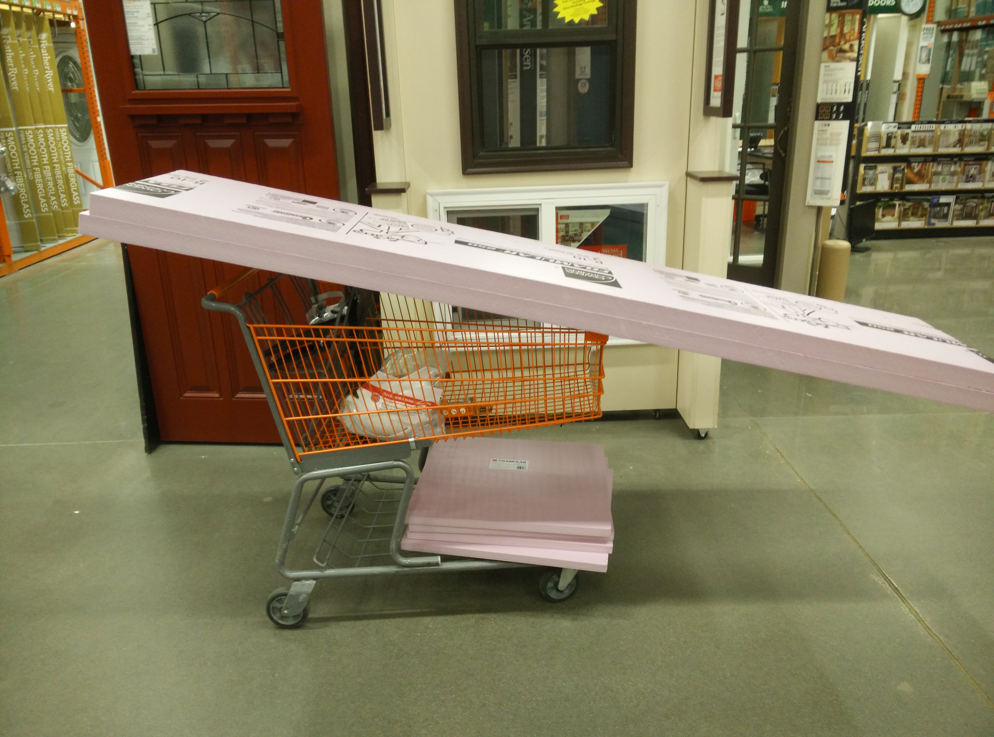
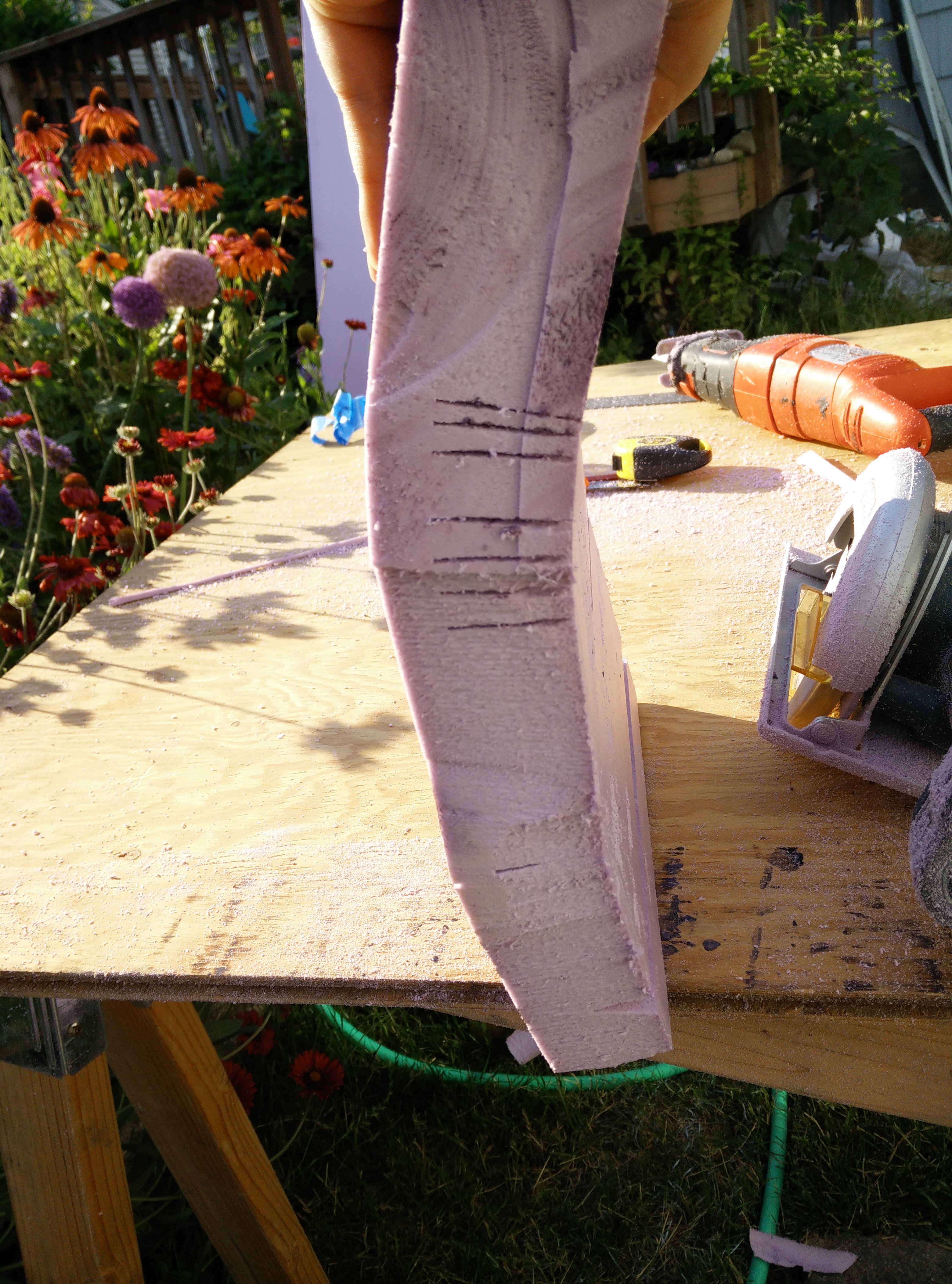
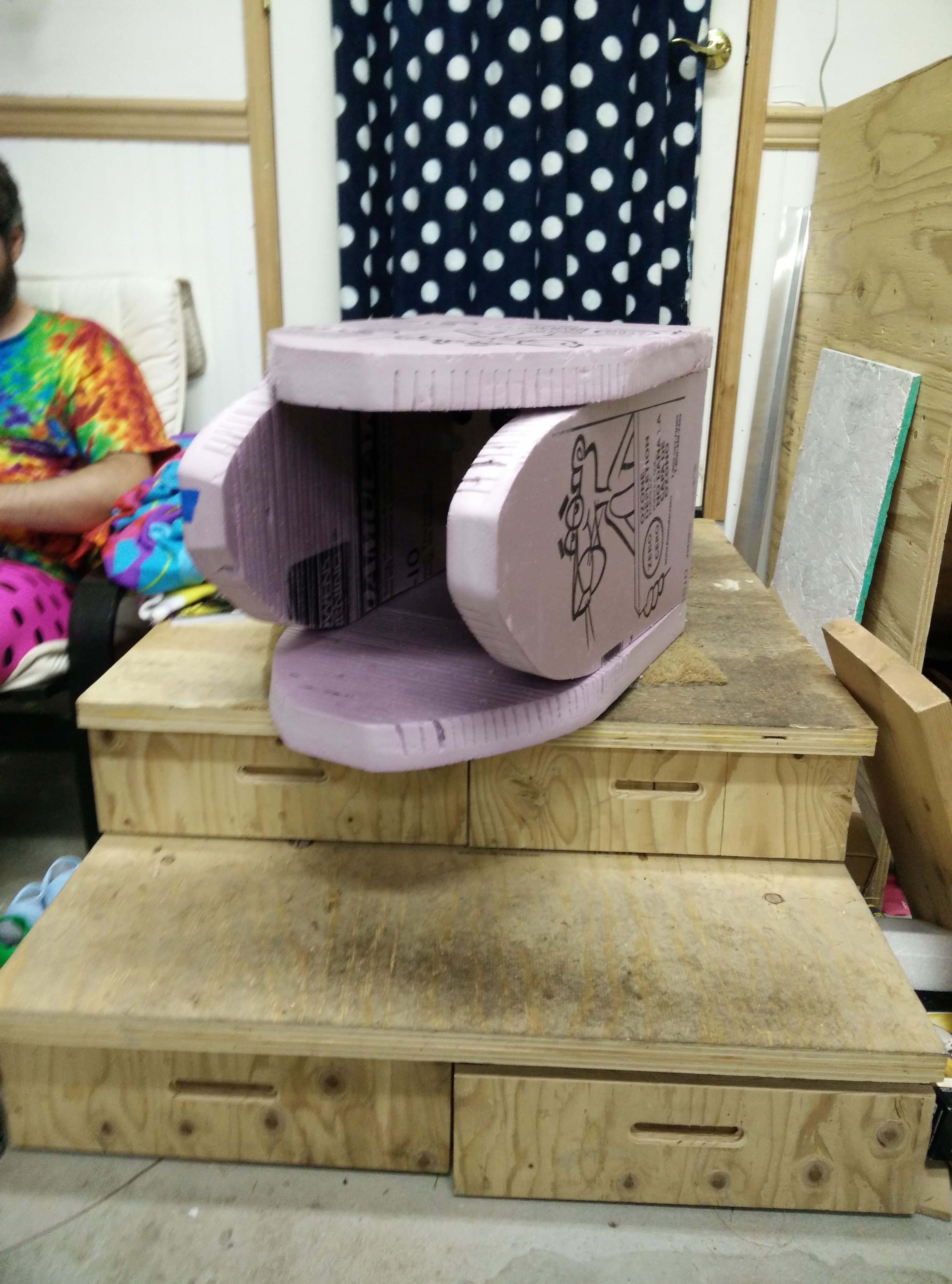
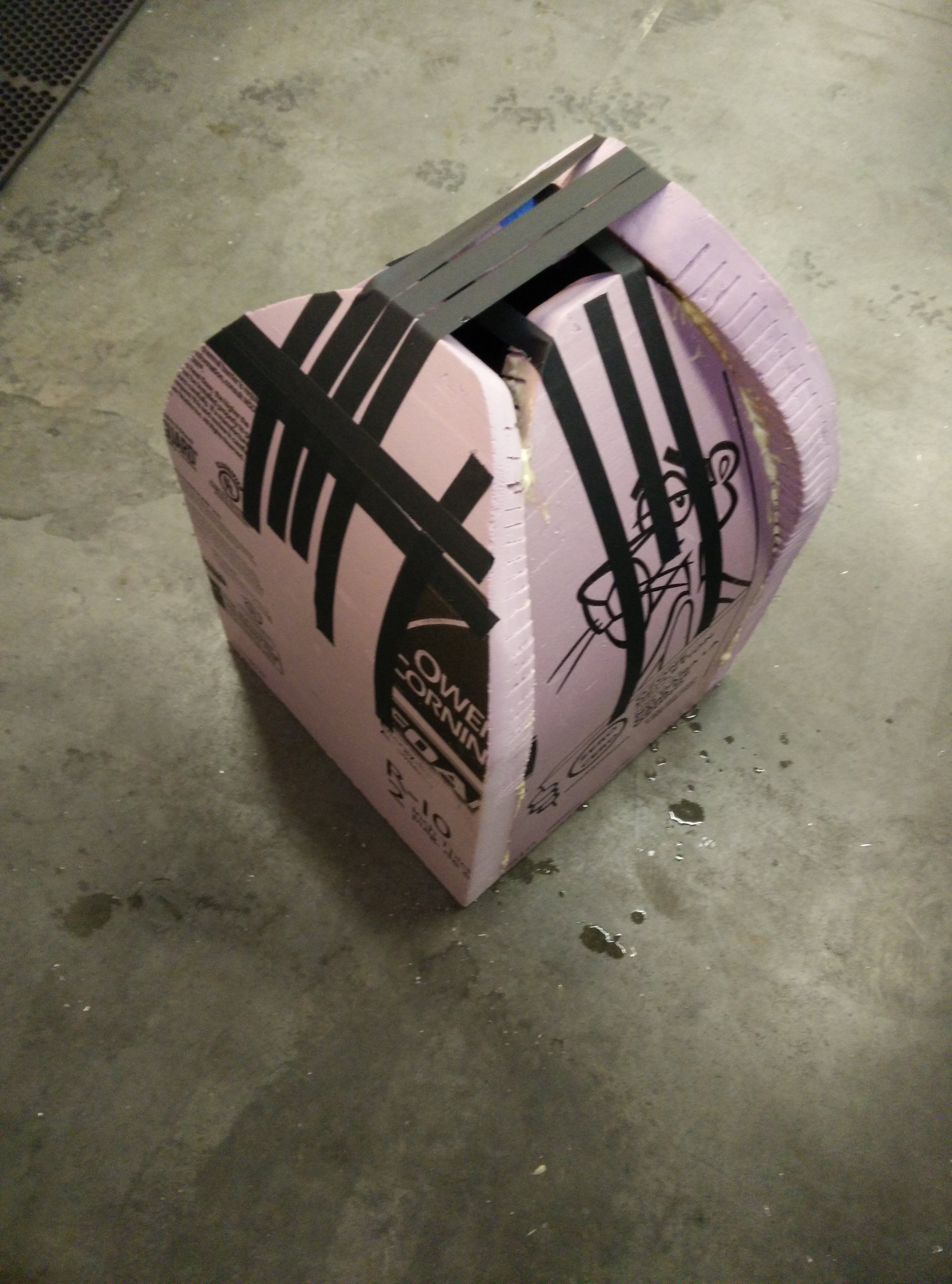
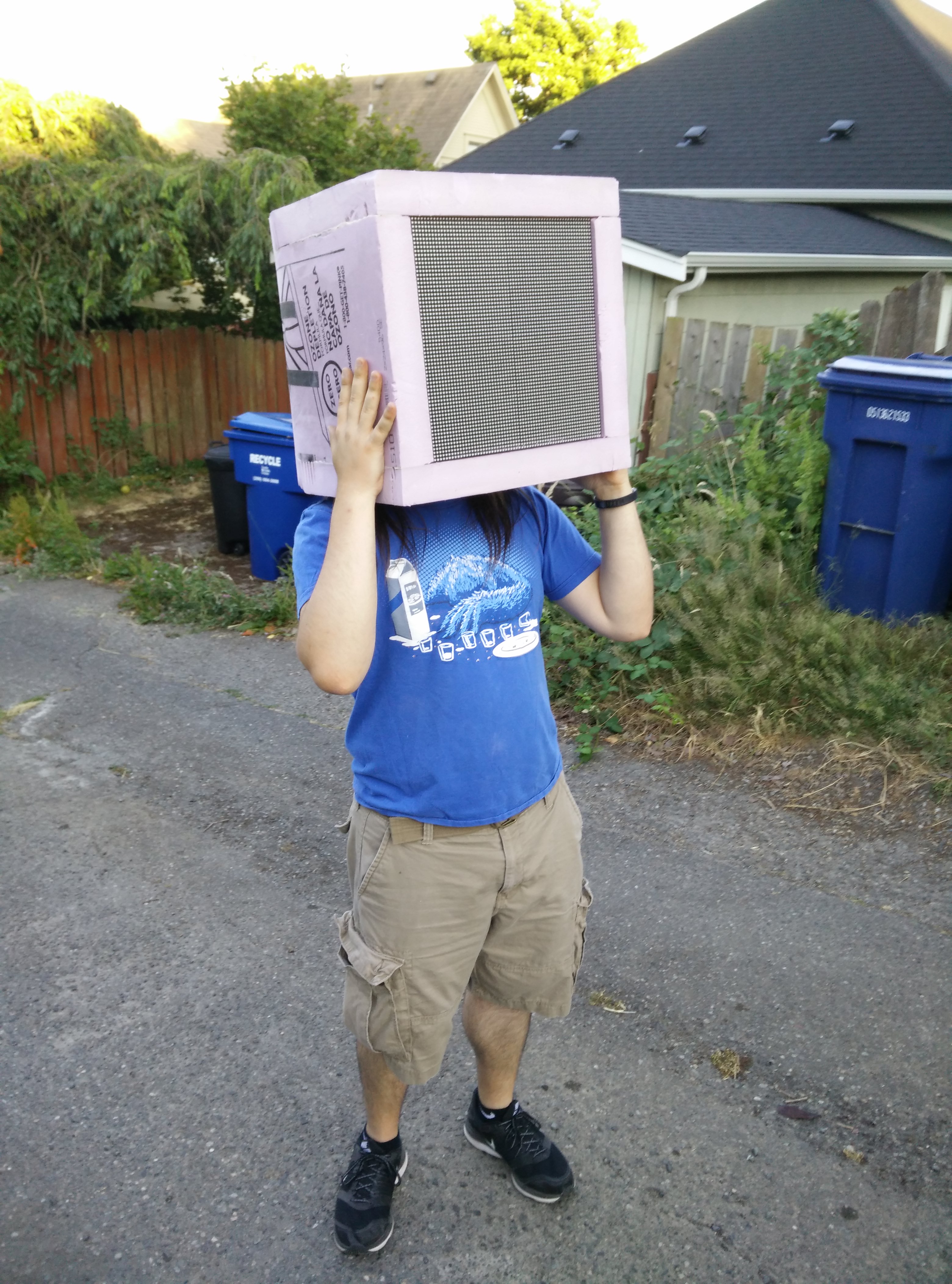
We then take a bunch of 2 inch thick pink housing foam and cut ~1 inch deep grooves into it so we can bend it into a rounded shape, and form it into a box:
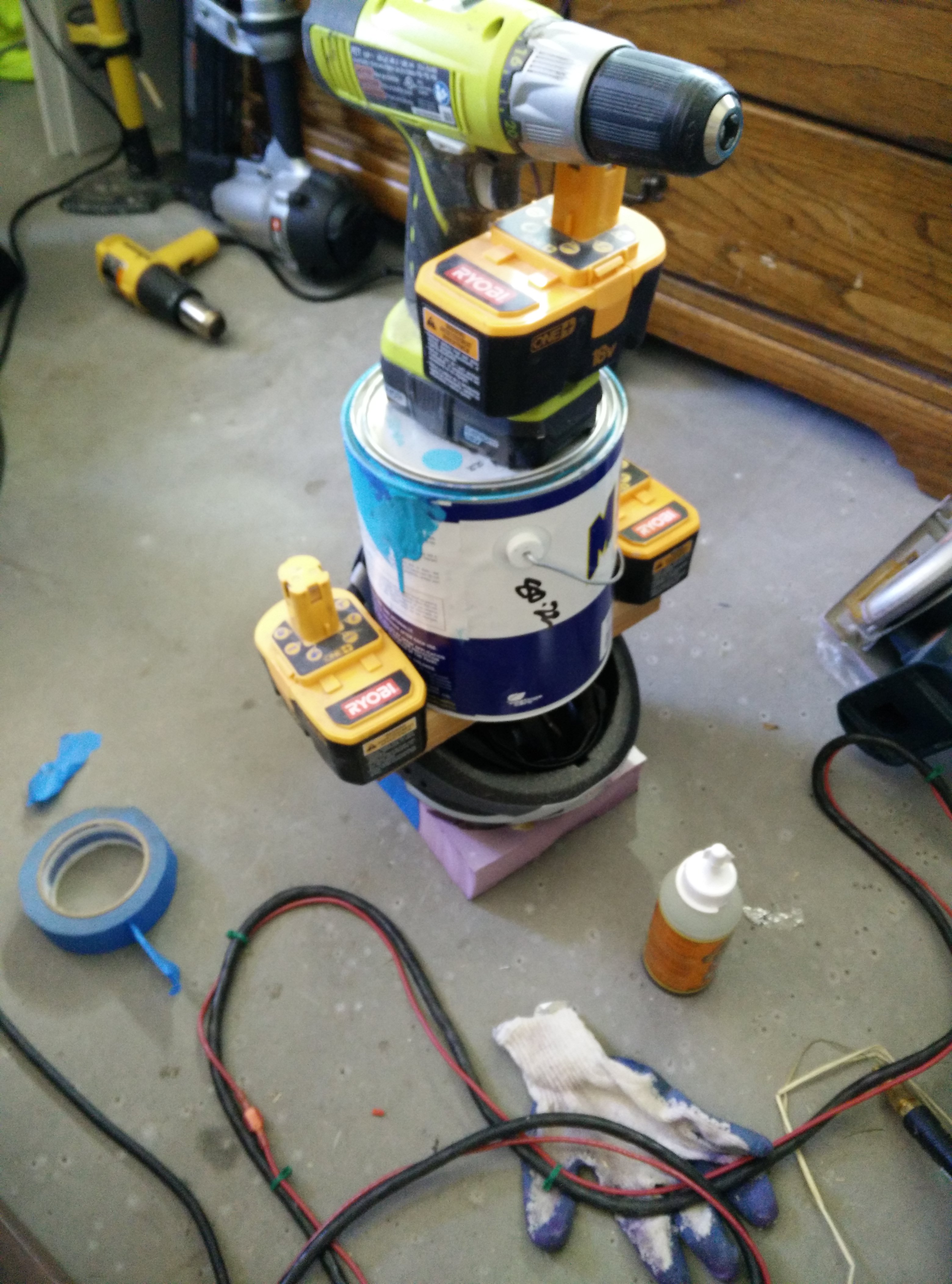
Next, using an excessive amount of gorilla glue, gaffers tape, and weights, everything is adhered together:
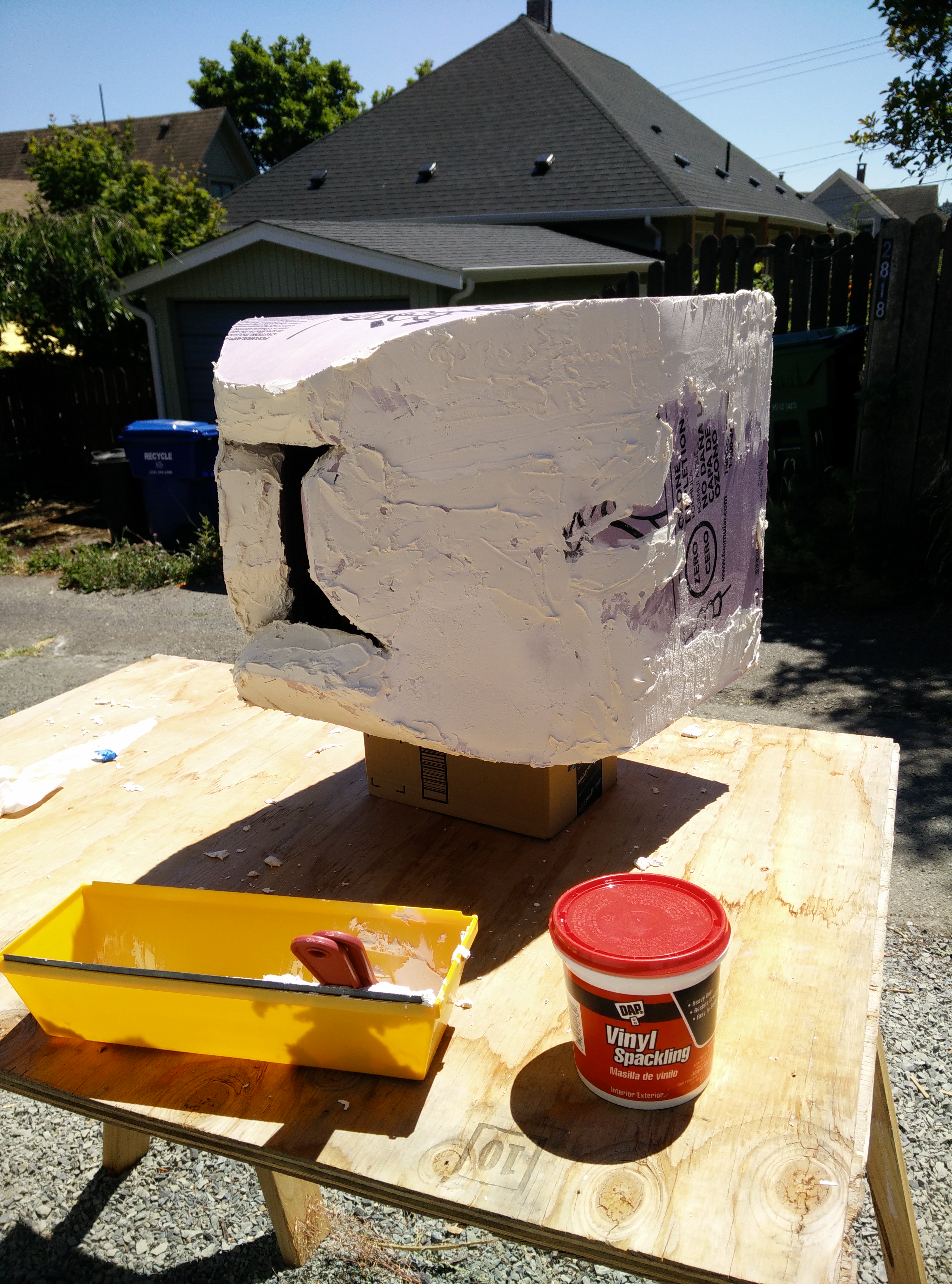
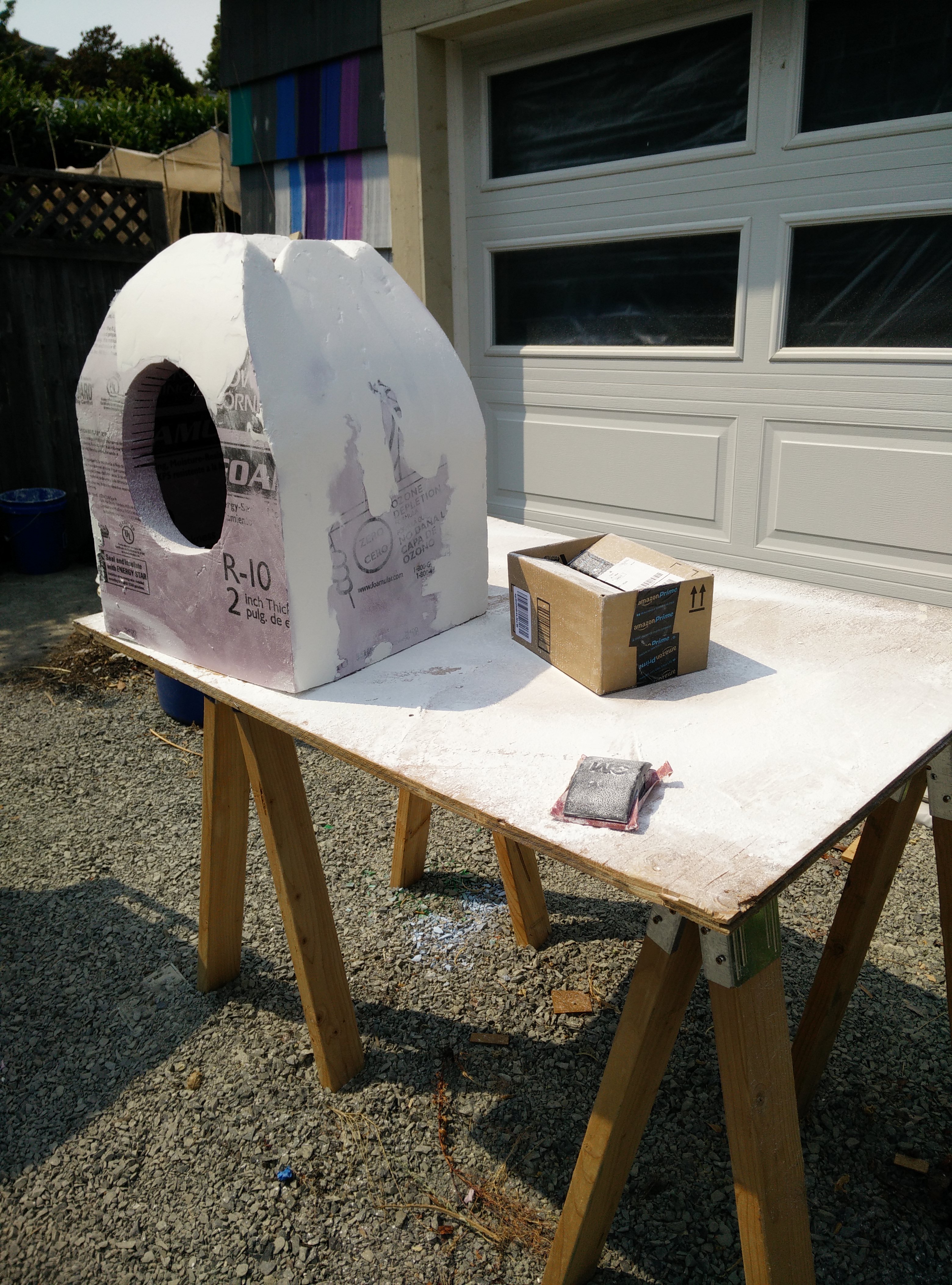
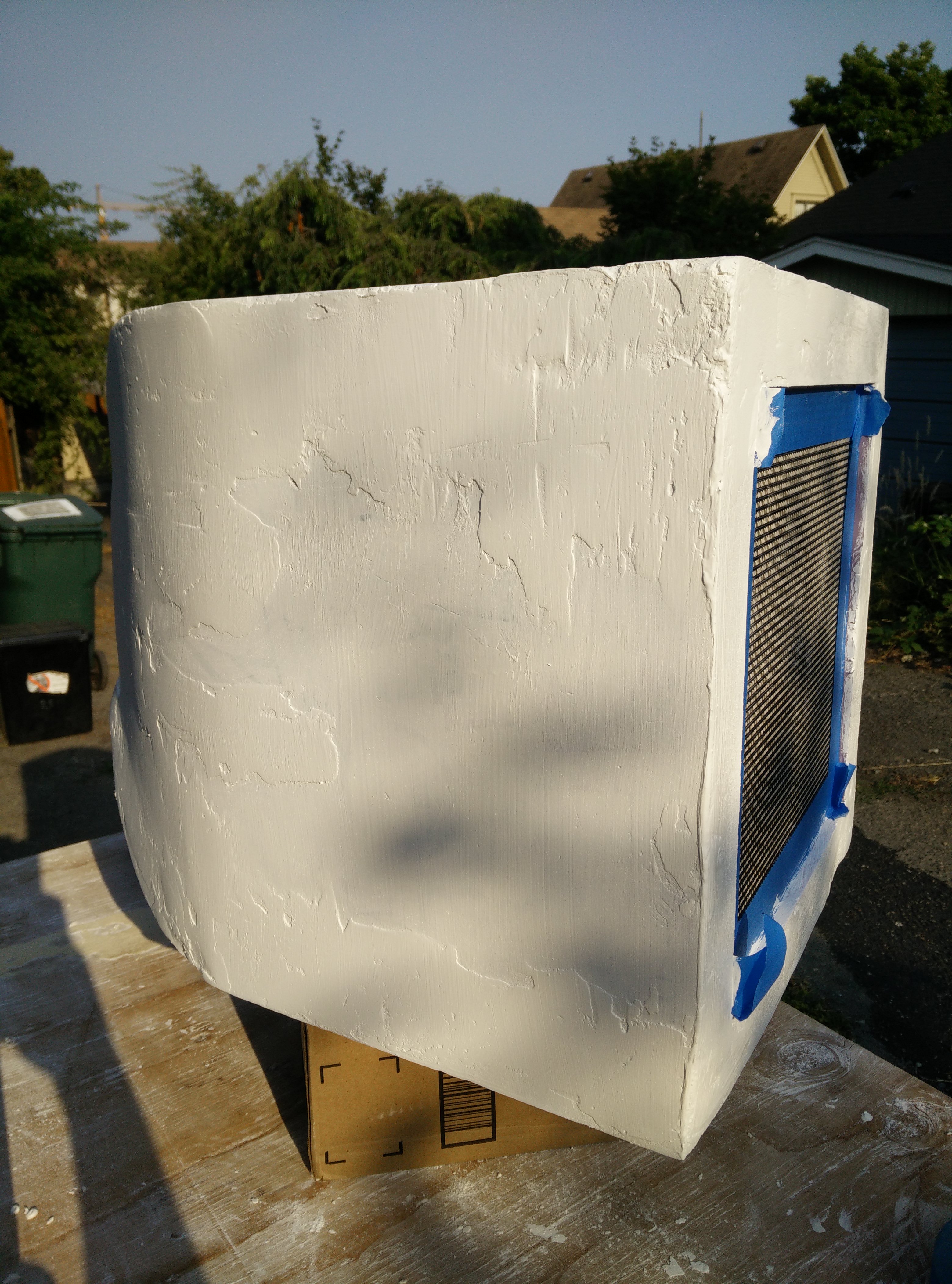
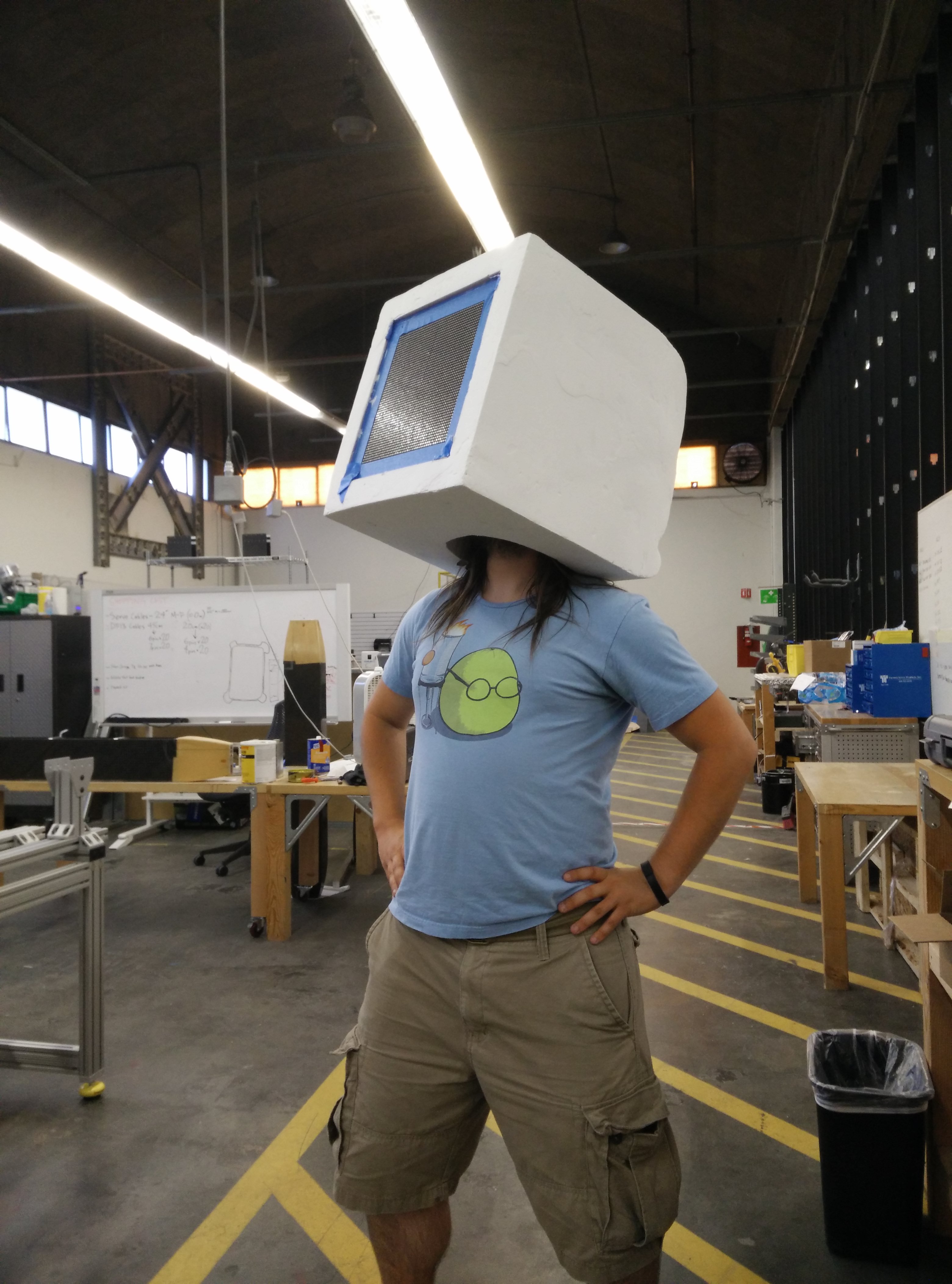
After gluing the box together, the foam is further carved down so there is as clean a seam as I can manage, and we spackle over all the gaps. Spackle turned out to be a terrible choice: it is both heavy on a helmet, and it takes a long time to dry between coats (and I was running out of time). The finish is pretty ugly, but it works!
Next up, the all-important tests of fit! Does my head fit through the hole on the bottom? Can I actually hold my head up under all this plaster? Can I see through the tiny camera hastily taped to the bottom of the helmet?
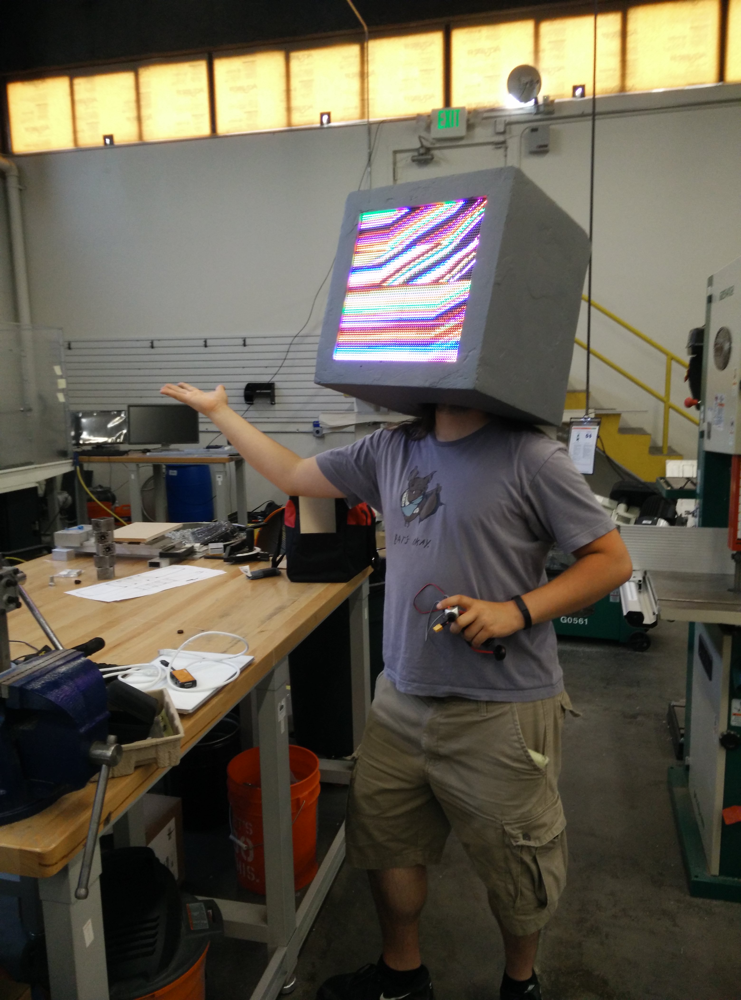
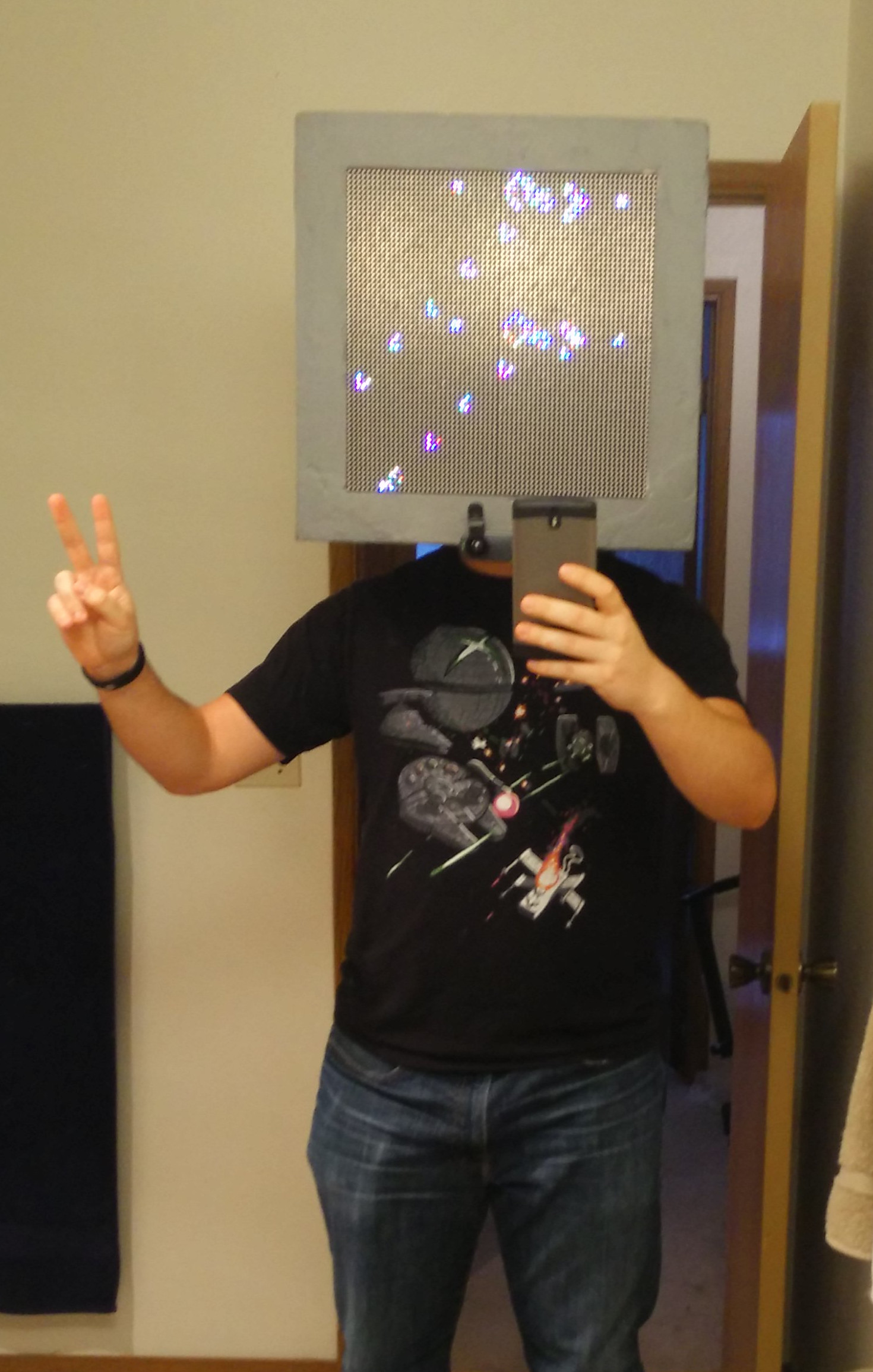
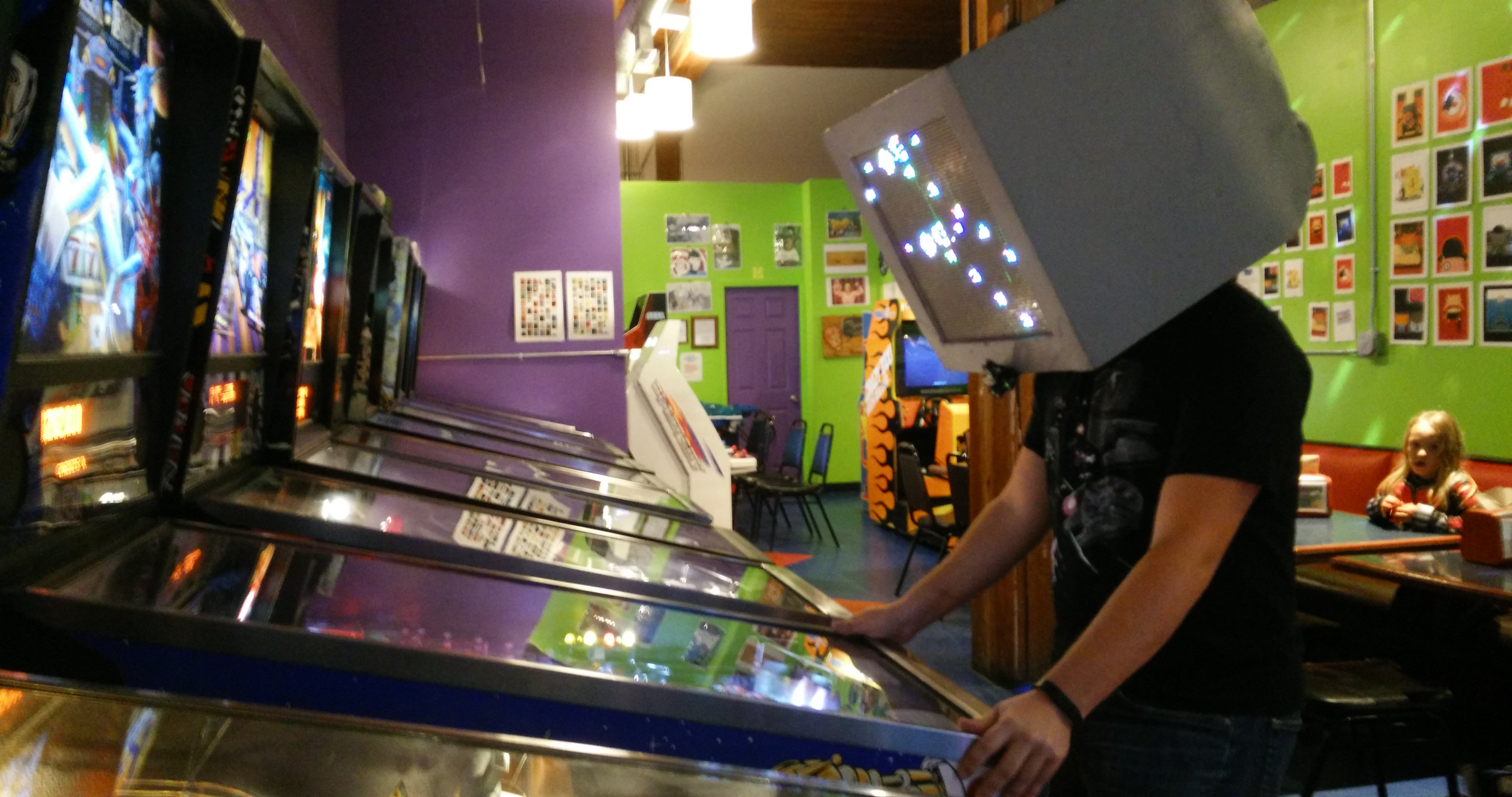
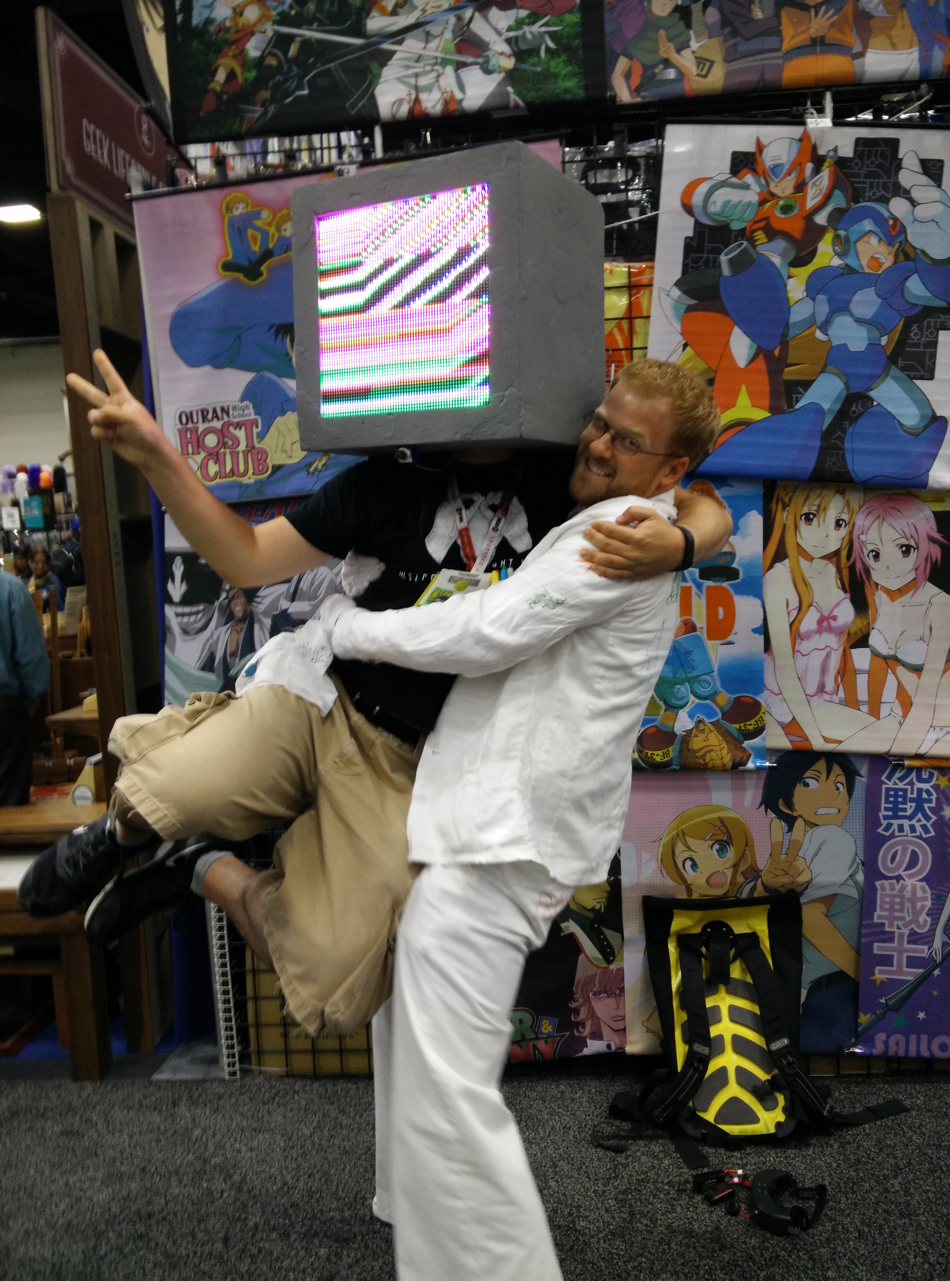
A few coats of paint are thrown on, and with that, we have the costume! Okay, obviously I didn't manage to build up any of the outfit beyond the head, but the head took up every moment of time I had before comic-con, so the head would have to do! The rainbow lines actually are because I wasn't able to get loading of images from the beaglebone to the FPGA working in time, so I miswired the display so that it was effectively colorful static. I was told the static shifted when I breathed on the wires, so the effect was at least interesting!
Epilogue
There was a lot which simply came together without it ever quite working as it was meant to - you'll note that I didn't even mention the interface between the beaglebone and the FPGA - that's because I never quite made it work due to a combination of inexperience and struggles with timelines. Rather than walk you through a half-remembered version of the project which didn't even work correctly, I figured I would instead have the next entree of the blog discuss my second attempt at controlling these LED matrix screens, and how I was much more successful! I even used modern tools which are still relevant!
To cap off what I got working on this project though - I got very slow interfacing working between the beaglebone and the FPGA through the tools provided with the logibone. This involved something called the external memory interface (EMIF) on the beaglebone and something called the wishbone bus in the FPGA. I won't pretend to fully understand the details of the implementation here though - I trusted the python bindings and provided verilog and got something which could update individual pixels well enough, but so slowly that full screen updates were, at best, choppy. Since small updates were reasonably quick, I made a Game of Life simulator and some pretty looking patterns to have something controlled on the screen (you can see this in the final row of pictures above!)
Another important detail I never had even when I was trying to display normally encoded images was called gamma correction. This meant that images looked strangely washed out on my display, and I wasn't clear why at the time.
I think that's everything! Thanks so much for reading!
